A partner you can trust
Choosing the right Delta Servo Motor is a practical engineering decision, not a catalog exercise. Because no source material was provided, I cannot verify a named expert’s quotation. The line below is an editorial rule of thumb, not a quote from a real person: “Choose the motor for the load you must control, not the largest number on its label.” That distinction matters.
Begin with the machine’s actual demands. Record the load mass, required speed, acceleration, duty cycle, and available supply voltage. A conveyor moving steady cartons needs different performance from a pick-and-place arm reversing every few seconds. Check the motor’s continuous torque, peak torque, rated speed, encoder resolution, and compatible drive. Peak torque can handle brief acceleration; it cannot replace adequate continuous capacity. Allow for friction, inertia, and heat. Small errors here add up.
Then consider the working environment and control setup. A motor beside a dusty packaging line may need different protection from one inside a clean cabinet. Confirm mounting dimensions, shaft fit, cable length, feedback type, and communication compatibility before ordering. Test the selected motor under realistic loads when possible. It may reveal a mismatch. This guide explains how to compare specifications, match a Delta Servo Motor to its servo drive, and avoid common selection mistakes. The final choice should fit the machine’s real operating conditions, not an idealized calculation alone.
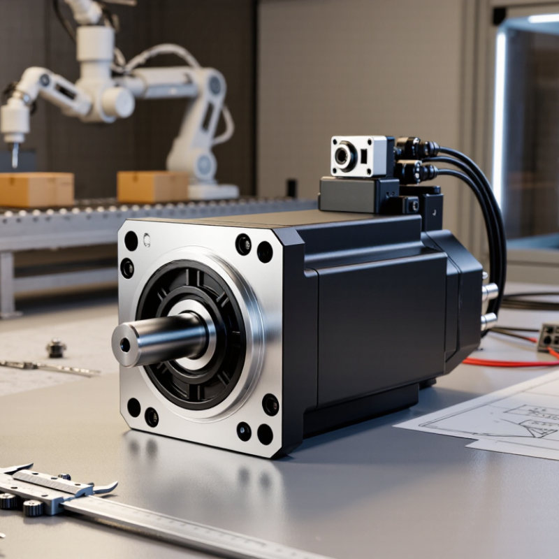
Before choosing a servo motor, define what the machine must do. Record the required travel, positioning accuracy, maximum speed, and cycle time. A pick-and-place axis moving a small part needs a different motion profile from a conveyor lifting a heavy load. Note how quickly the axis must accelerate and stop, too. Those transitions can demand more torque than steady movement.
Estimate the load’s inertia, including pulleys, couplings, and the driven mechanism. Compare peak torque during acceleration with the motor’s continuous torque over the full duty cycle. A motor sized only for the heaviest load may still overheat during repeated starts. Small details matter. Early estimates are rarely perfect, so leave room to verify them against real machine data.
Operating conditions shape the choice as much as motion does. Check ambient temperature, available supply voltage, mounting position, and exposure to dust, oil, or vibration. Confirm that the motor and drive can handle the required feedback, braking, and communication interfaces. If the axis runs near people or sensitive equipment, consider noise and smooth low-speed control. A clean workshop test may not reflect a warm cabinet or a machine running all day. Revisit assumptions after measuring the actual cycle; that step is easy to postpone, and costly to skip.

Define the Motion Requirements and Operating Conditions
This illustrative cycle shows how speed and torque demand can change during a move. Use the full duty cycle to determine required speed range, peak torque, and RMS torque; also account for load inertia, ambient temperature, and operating conditions. Verify the resulting requirements against the selected motor and drive specifications.
Servo motor types differ in rotor inertia, torque delivery, and response speed. Low-inertia models accelerate quickly, making them suitable for pick-and-place arms and compact packaging axes. Higher-inertia models can better tolerate changing loads, such as a heavy conveyor or rotary table. Not sure? Check the machine’s load-to-motor inertia ratio before choosing; a mismatch can cause vibration or sluggish starts.
Compare ratings under the conditions your machine will actually face. Rated torque describes continuous output, while peak torque is available only for short periods. A motor rated for 2 N·m continuously may handle brief 6 N·m peaks, but confirm the drive’s limits and overload duration. Speed matters too. A high maximum speed is useful only if the motor can maintain the required torque there. Heat builds fast.
Check feedback and protection details alongside power ratings. Incremental encoders can suit simpler positioning, while absolute encoders retain position data after power loss. Match encoder resolution to the accuracy the mechanism needs; finer resolution alone cannot fix backlash. Review the drive’s voltage, current, and communication compatibility, then check the motor’s IP rating against dust, oil mist, and washdown exposure. A catalog comparison is a good start, but real duty cycles can be messier than the neat figures suggest.
Choosing a servo motor starts with the load at the motor shaft, not the machine’s headline speed. Measure steady torque, acceleration torque, peak speed, and operating time. A conveyor may need little torque while moving, then demand much more when a loaded belt starts. That brief demand matters.
Calculate the required torque across the full motion cycle, including friction, inertia, and any gearbox ratio. Compare the cycle’s effective torque with the motor’s continuous rating, then check peak torque and speed against its limits. A motor that meets peak torque but overheats during repeated cycles is undersized. Do not guess. The U.S. Department of Energy’s 2014 motor systems sourcebook reports that motor-driven systems use about 68% of U.S. manufacturing electricity, underscoring the practical value of selecting and operating them efficiently.
Check the motor’s torque-speed curve at the actual supply and drive conditions; available torque can fall as speed rises. Also compare load inertia with motor inertia and confirm that the drive can handle acceleration and braking. I would not treat a catalog torque figure as a guarantee: friction, belt tension, and product weight vary on real machines. Leave sensible margin, but avoid oversizing so much that the motor runs inefficiently or costs more than needed. DOE, Improving Motor and Drive System Performance: A Sourcebook for Industry, 2014.
Choosing the right servo motor is only half the job. Its servo drive must support the motor’s rated voltage, continuous current, and peak current. Check the exact motor-and-drive compatibility table rather than matching parts by size alone. A mismatch can cause alarms, weak acceleration, or excess heat. Allow for the machine’s supply voltage and real load, too.
Tips: Confirm the feedback type, connector, and resolution before ordering. Check communication needs and cable length. Keep a little current margin, but do not oversize without a reason.
Feedback selection affects how accurately the system knows the motor’s position and speed. Verify that the drive can read the motor’s encoder or other feedback device, and that its settings match the feedback specifications. After wiring, test direction and feedback readings at low speed before running the full machine. Watch for unstable motion, unexpected noise, or repeated alarms. In practice, a datasheet match can still leave questions about tuning or load inertia; I would verify those details with a controlled test, not assume the first setup is perfect.
| Selection Dimension | What to Determine | Motor and Drive Matching | Feedback System Check | Practical Verification |
|---|---|---|---|---|
| Power supply and voltage class | Available AC supply, phase configuration, and the machine’s electrical limits. | Choose a drive with an input-voltage class compatible with the supply and a motor rated for that drive’s output voltage. Common industrial classes include 200–240 V AC and 380–480 V AC; actual limits vary by drive. | Confirm the feedback device is supported by the selected drive, not just by the motor. | Check the drive nameplate and manual for permitted input voltage, frequency, and phase configuration. |
| Continuous and peak torque | Required load torque during normal operation and the highest short-duration torque during acceleration or disturbance. | The motor’s continuous torque must cover the calculated continuous requirement. Check that both motor and drive can provide the required peak torque for the required duration. | Ensure feedback and control settings support the intended torque-control or motion-control mode. | Include friction, gravity, transmission efficiency, and acceleration torque in the load estimate; do not size from rated power alone. |
| Speed and power | Required operating speed, maximum speed, and torque demand across the operating range. | Verify that the motor’s rated and maximum speeds cover the application and that the drive can supply the required current at those speeds. Mechanical power is approximately torque × angular speed. | Confirm the feedback device’s specified speed limit and the drive’s supported feedback input rate. | Review the motor torque-speed curve; available torque can decrease at higher speeds because of voltage and current limits. |
| Load inertia and acceleration | Load inertia referred to the motor shaft, acceleration time, and required stopping behavior. | Calculate acceleration torque using the total inertia referred to the motor shaft and the requested angular acceleration. Confirm the resulting peak demand is within motor and drive limits. | Position-loop performance depends on feedback resolution, update rate, and correct drive tuning. | Use the transmission ratio to reflect load inertia to the motor shaft; verify the manufacturer’s inertia and tuning guidance rather than relying on a universal inertia-ratio limit. |
| Feedback type | Whether the application needs speed feedback, incremental position, or position retained at power-off. | Select a motor and drive combination that supports the same feedback technology and electrical interface. | Incremental encoders typically provide relative position and require referencing after power-up unless another reference method is used. Absolute encoders can report position after power-up, subject to the system’s configuration and protocol. | Check encoder type, resolution, supply requirements, wiring, and whether the drive can read the specific feedback device. |
| Feedback protocol and commutation | Encoder signal format or serial protocol, plus the signals needed for motor commutation. | Drive support must explicitly include the motor’s feedback interface; matching connector shape alone does not establish compatibility. | Incremental A/B/Z signals, Hall signals, resolver signals, and serial absolute-encoder protocols are not interchangeable. Serial protocols may be implementation-specific. | Confirm the exact protocol, pinout, cable and connector requirements, and any required motor-identification or commutation data in the drive documentation. |
| Mounting and environment | Frame size, shaft and flange dimensions, installation orientation, ambient temperature, and exposure to dust or moisture. | Match mechanical dimensions and confirm the drive and motor are rated for the machine’s electrical and thermal conditions. | Check feedback-device temperature limits and cable routing requirements, especially near power cables or other sources of electrical noise. | Verify the motor’s enclosure rating, allowable ambient conditions, cooling method, and mounting dimensions against the application. |
| Holding brake and safety | Whether the axis must hold position when stopped or when motor power is removed. | If a brake is required, confirm the motor includes a compatible brake and that the drive or control system provides the correct brake-control arrangement. | Feedback indicates position; it does not mechanically hold the load. A motor brake is generally intended for holding, not repeated dynamic stopping unless specifically rated for it. | For vertical or gravity-loaded axes, assess the risk of load movement and follow the machine’s braking and safety requirements. |
Start with the installation, not the catalog. Measure the machine’s peak and continuous load, available supply voltage, mounting space, and shaft alignment. A motor that fits electrically may still overheat in a cramped cabinet. The U.S. Department of Energy’s 2014 motor-systems sourcebook estimates that motor-driven systems use about 68% of U.S. manufacturing electricity. That figure makes efficiency and correct sizing practical concerns, not minor specifications.
Check communication before ordering. Confirm the controller’s supported fieldbus, feedback device, cable pinout, and update rate. A protocol name alone does not guarantee compatibility; verify the exact interface and configuration tools in the equipment documentation. During installation, keep encoder and power cables separated where specified, and ground the system as the manufacturer directs. Small details matter. A loose shield can create intermittent position errors that appear only when nearby equipment starts.
Protection requirements depend on the actual environment. Check enclosure rating, ambient temperature, vibration, overload limits, and braking needs against the machine’s duty cycle. The International Energy Agency’s 2011 report, Energy-Efficient Electric Motor Systems, estimates that electric motor systems consume 46% of global electricity. Even so, efficiency figures cannot replace application checks. Dust, washdown, or repeated rapid stops may change the right configuration. It is easy to overlook cable routing during a bench test; inspect it again after the motor is mounted and moving.
This content is restricted to site members. If you are an existing user, please log in. New users may register … LEARN MORE “Lighting Power & Control-Signal Cable”
We are here to help. You can contact us or create an account online to have access to special products, technical specifications and our new online quote tool.
ELECTRO CABLES
9 Riverside Drive
P.O. Box 276
Trenton, Ontario
CANADA K8V 5R5
N.A. Toll Free: 888-ELECTRO
(1-888-353-2876)
World: 613-394-4896
Fax: 613-394-4101
Email: sale@machinecables.com
We manufacture cables that are certified by the Canadian Standards Association (CSA), listed by Underwriters Laboratories and/or listed by Intertek (ETL).
Our quality management system is registered to ISO 9001: 2015. Our team is dedicated to consistently providing quality service and products to our customers.

© 2025 ELECTRO CABLES • SITE BY SNAP 360•