A partner you can trust
Choosing the right Rmu Electrical Panel starts with understanding the network it must serve. Voltage, rated current, fault level, and installation environment all shape the selection. A panel for a compact indoor substation may not suit a coastal site exposed to moisture and salt. Small details matter.
Begin by matching the panel’s ratings to the system design, not just the present load. Consider future expansion, switching frequency, cable connections, and available maintenance access. Ask suppliers for clear documentation on insulation, internal arc classification, operating mechanisms, and routine testing. These details help engineers compare products beyond appearance and price.
Reliability also depends on installation quality and ongoing care. Check that the panel fits the room layout, ventilation needs, and cable-bending space. Confirm compatibility with protection relays and remote monitoring systems where required. A qualified electrical engineer should review the design against project specifications and applicable standards. No single specification guarantees a trouble-free installation; operating conditions and maintenance practices still count. That point is easy to overlook.
This guide explains the main selection criteria, common trade-offs, and questions to raise with manufacturers. It also highlights areas where buyers should pause and verify claims, especially when comparing compact designs or unfamiliar features. The best choice is not automatically the newest or least expensive model. It is the one that meets documented requirements, suits the site, and can be supported throughout its service life.
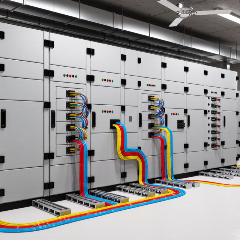
IEC 62271-200:2021 covers metal-enclosed switchgear and controlgear rated above 1 kV and up to 52 kV AC. That range is a boundary, not a recommended RMU setting. Start with the network’s nominal voltage, then verify the panel’s rated voltage against the utility specification. An 11 kV feeder, for example, commonly uses 12 kV-class equipment. Check that its insulation withstand suits the system’s highest operating voltage, not just the number on the feeder drawing. Confirm frequency, earthing method, and short-circuit level too. Small details matter: a 24 kV panel may fit one site but be an unnecessary mismatch for another. Voltage first. But not voltage alone.
The IEA’s 2023 Electricity Grids and Secure Energy Transitions report says more than 80 million kilometres of grids must be added or refurbished by 2040—roughly the length of today’s global grid. That figure signals widespread network renewal; it does not specify an RMU voltage. Treat it as context, not a sizing rule. Ask the utility for maximum operating voltage and insulation requirements, then compare them with the panel’s IEC-rated values and test documentation. Confirm installation altitude and indoor or outdoor conditions, since these can affect insulation performance. A practical mistake is treating “within 1–52 kV” as proof of suitability. It is not. I would still leave one line in the design review for a second check: drawings, protection settings, and nameplate ratings do not always agree.
A 630 A-class rating is a starting point, not a complete selection rule. It describes the rated continuous current under specified conditions; it does not confirm that every feeder will run safely at 630 A. Compare expected demand, transformer capacity, load growth, and the RMU’s installation conditions. A compact room with limited ventilation may affect equipment performance. Check the manufacturer’s stated ratings and applicable test data.
Fault-current studies are just as important. Use the calculated prospective short-circuit current at the installation point to check the RMU’s short-time withstand rating, duration, and peak making current. These values must suit the protection system’s clearing time. For example, a unit rated for one second may not be suitable if a fault could persist longer. Verify the circuit-breaker or fuse coordination with the study, not from the 630 A figure alone. Small details matter.
Review the assumptions. Utility data, cable impedance, and future network changes can shift fault levels. A tidy spreadsheet can still miss a real site constraint; that is worth checking twice. Ask the electrical engineer to confirm both normal-load margins and fault-duty margins before specifying the panel. If the study is uncertain, document the uncertainty and revisit the selection when better data becomes available.
Compare Air- and Gas-Insulated Designs for Site and Maintenance Needs
Air-insulated RMUs use air as the insulation medium and often need more installation space. Their accessible compartments can make routine visual checks straightforward. But dust, moisture, and room conditions deserve attention. A narrow service aisle or damp equipment room may complicate maintenance.
Gas-insulated designs place live parts inside sealed compartments, which can help protect them from environmental exposure and reduce the footprint. That can matter in compact substations or crowded utility rooms. Maintenance may require trained technicians and procedures for checking the sealed system. The smaller panel is not automatically the easier choice. Consider service access, outage planning, and local support before deciding. A design that looks ideal on a drawing can feel awkward when a technician needs to reach a cable compartment.
Choosing an RMU is not just about rated voltage or compact dimensions. The switching sequence must match the site’s operating procedure. Check that the earthing switch cannot close while the circuit is energized, and that access doors remain secured until the equipment is earthed. Verify mechanical or key interlocks during a witnessed operating test, not only on a drawing. Small details matter.
Check the applicable IEC requirements for the complete assembly. IEC 62271-200 covers metal-enclosed switchgear above 1 kV up to 52 kV, including internal-arc classification. IEC 62271-102 addresses disconnectors and earthing switches, while IEC 62271-103 covers switches. For switch-fuse combinations, review IEC 62271-105. Ask for type-test evidence, interlock diagrams, and clear instructions for normal and emergency operation. Confirm the stated internal-arc classification suits the room layout and operator access.
The IEA’s 2023 report, Electricity Grids and Secure Energy Transitions, says 80 million kilometres of grids must be added or replaced by 2040 in its net-zero pathway. That scale makes dependable switching practices increasingly important. Still, a standards checklist can miss awkward site conditions: cramped access, poor lighting, or unclear labels. Walk through the actual switching sequence with operators before approval. A careful review is practical, not perfect.
How to Choose the Right RMU Electrical Panel
Environmental ratings should match the panel’s actual location, not just the project specification. Check the enclosure’s stated protection level against dust, moisture, temperature, and possible corrosive exposure. A sheltered indoor room and a damp outdoor kiosk have different demands. Ask for documentation confirming the rating applies to the complete assembly. A label alone may not answer every installation question.
Measure the available space, cable entry points, access clearance, and lifting route before choosing a unit. Confirm the panel suits the site’s voltage, current, fault level, and operating requirements with a qualified electrical professional. Small layout details matter. A cable trench in the wrong place can turn a straightforward installation into expensive rework. I would not assume existing drawings reflect current site conditions; they sometimes do not.
Tips: Request service intervals, spare-parts availability, response times, and clear warranty terms in writing. Ask who can provide technical support after commissioning, and whether routine checks require specialist tools. Keep those answers with the equipment records. Good support is practical, not just a promise.
| Selection Factor | What to Assess | Ratings or Information to Verify | Practical Check Before Purchase |
|---|---|---|---|
| System voltage | Confirm the network’s nominal voltage and the highest voltage for the equipment. | Rated voltage and insulation levels must suit the system and applicable utility requirements. Common distribution classes include 12 kV, 24 kV, and 36 kV, but availability and suitability depend on the network. | Match the panel nameplate data and test documentation to the project’s single-line diagram and utility specifications. |
| Rated current and fault duty | Check normal load current, transformer or feeder requirements, and the network’s prospective short-circuit current. | Verify rated normal current, short-time withstand current and duration, and peak withstand current. These are separate ratings and must meet the system study and protection design. | Ask the electrical designer or utility to confirm the fault level at the installation point; do not select from load current alone. |
| Indoor or outdoor location | Consider exposure to rain, dust, condensation, direct sunlight, flooding, and corrosive or polluted air. | Confirm the manufacturer’s declared indoor or outdoor suitability and the IP rating of each relevant enclosure or compartment under IEC 60529. | Check whether the stated IP rating applies to the complete installed assembly, cable-entry areas, doors, and ventilation openings—not just a component. |
| Ambient temperature and altitude | Compare site conditions with the switchgear’s declared service conditions, including seasonal extremes and site elevation. | IEC 62271-1 specifies normal service conditions; common reference limits include a maximum ambient temperature of 40°C and altitude up to 1,000 m. Operation outside declared limits may require special design or derating. | Provide the manufacturer with the site’s minimum and maximum temperatures, altitude, solar exposure, and any enclosure-heating or ventilation requirements. |
| Moisture, condensation, and pollution | Assess coastal salt, industrial contamination, humidity, condensation, and the risk of water ingress. | Verify any required insulation, corrosion protection, anti-condensation measures, and environmental limits stated in the technical documentation. | Ask how heaters, drainage, cable sealing, and cleaning or inspection requirements are handled for the specific site conditions. |
| Internal arc protection | Determine whether personnel may be present near the switchgear and which sides are accessible during operation. | Where required, check the declared internal-arc classification, test current and duration, and accessible sides. Classification and test conditions should be documented for the exact assembly configuration. | Confirm that the tested configuration matches the proposed panel, installation clearances, pressure-relief path, and room layout. |
| Installation space and access | Review room dimensions, aisle widths, door openings, lifting routes, cable trench position, and operating access. | Obtain the equipment outline, foundation or fixing details, minimum clearances, cable bending requirements, and any rear or side access requirements. | Check dimensions against the latest building drawings and confirm that the unit can be delivered, positioned, connected, and maintained safely. |
| Cable connections and configuration | Match the number and type of incoming, outgoing, transformer, and metering circuits to the network design. | Verify cable termination type, conductor range, phase spacing, earthing provisions, voltage indication, and any protection or metering options. | Have the supplier confirm compatibility with the specified cables and accessories, including termination space and installation instructions. |
| Operating mechanism and interlocks | Consider local or remote operation, switching frequency, operating personnel, and the required safety sequence. | Review the switching-device ratings, operating method, mechanical and electrical interlocks, and the manufacturer’s operating procedures. | Request a demonstration or operating sequence review and verify that interlocks support the site’s approved switching rules. |
| Standards and documentation | Confirm compliance with the project specification, local regulations, and the utility’s acceptance requirements. | For medium-voltage switchgear, review applicable standards such as IEC 62271-1 and IEC 62271-200, along with type-test and routine-test documentation where required. | Check that certificates and test reports cover the offered ratings and configuration, and request drawings, manuals, and nameplate details before approval. |
| Maintenance and service support | Evaluate maintenance tasks, expected service life, spare-parts availability, response times, and technician access. | Obtain the maintenance schedule, recommended inspection intervals, spare-parts list, warranty terms, and service coverage for the installation region. | Confirm who will commission and service the equipment, how faults are supported, and whether specialist tools or training are needed. |
| Total installed cost | Compare the complete project cost rather than the panel purchase price alone. | Include transport, foundations, cable terminations, protection equipment, installation, testing, commissioning, and ongoing service needs. | Request a clearly itemized quotation and identify exclusions, lead times, and any site work required from the purchaser. |
This content is restricted to site members. If you are an existing user, please log in. New users may register … LEARN MORE “Lighting Power & Control-Signal Cable”
We are here to help. You can contact us or create an account online to have access to special products, technical specifications and our new online quote tool.
ELECTRO CABLES
9 Riverside Drive
P.O. Box 276
Trenton, Ontario
CANADA K8V 5R5
N.A. Toll Free: 888-ELECTRO
(1-888-353-2876)
World: 613-394-4896
Fax: 613-394-4101
Email: sale@machinecables.com
We manufacture cables that are certified by the Canadian Standards Association (CSA), listed by Underwriters Laboratories and/or listed by Intertek (ETL).
Our quality management system is registered to ISO 9001: 2015. Our team is dedicated to consistently providing quality service and products to our customers.

© 2025 ELECTRO CABLES • SITE BY SNAP 360•