Electro Cables
Login

7 Tips for Choosing the Right Wire Mesh Cable Tray

Choosing the right wire mesh cable tray is more than selecting a convenient metal basket. It affects cable support, airflow, installation time, and long-term maintenance. In real projects, a tray may look suitable in a catalog yet become crowded after only a few cables are installed. That assumption deserves questioning.

This guide presents seven practical tips based on common installation experience and engineering principles. It examines cable load, tray width, wire diameter, surface finish, environmental exposure, accessories, and grounding considerations. A tray installed in a dry office cannot be judged like one placed near moisture, chemicals, or outdoor equipment. Small details matter. Sharp edges can damage insulation. Weak couplers can create alignment problems. Poor sizing can force expensive changes later.

Reliable selection begins with verified information. Product drawings, load tables, material specifications, and applicable electrical requirements should be reviewed before purchase. Manufacturer data is useful, but it should not replace project-specific judgment. Cable weight, span length, support spacing, and future expansion all deserve attention. A practical review also considers how technicians will pull, separate, and inspect cables inside the tray. Sometimes, the cheapest option becomes costly after installation. Sometimes, an oversized system wastes valuable space. The best choice balances safety, performance, access, and budget. These seven tips offer a clear starting point, while leaving room for careful reflection on each project’s actual conditions.
7 Tips for Choosing the Right Wire Mesh Cable Tray

What a Wire Mesh Cable Tray Is and Where It Is Used

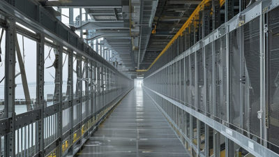
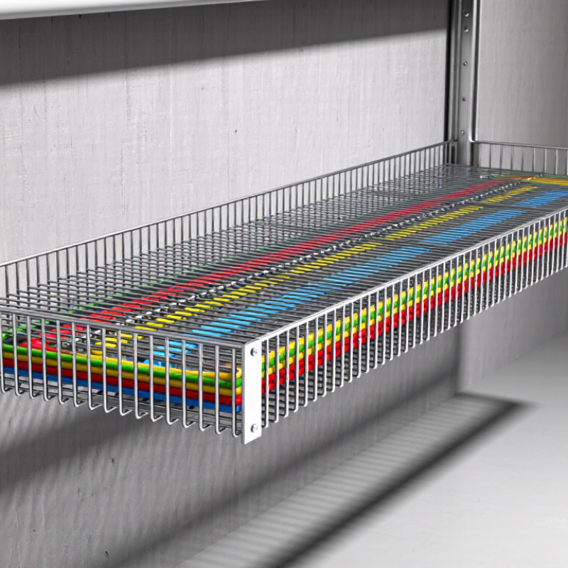
A wire mesh cable tray is a ventilated support system for power, control, and data cables. Its welded steel grid lets air circulate around cable bundles. This can reduce heat buildup and make inspection easier. It is not a magic fix.

It is commonly used in data centers, factories, commercial buildings, tunnels, and renewable energy facilities.

The IEA reported that data centers used about 460 TWh of electricity worldwide in 2022. That figure could reach 620–1,050 TWh by 2026.

Better cable organization therefore matters more as equipment loads increase. Choose seven points carefully: load capacity, wire diameter, corrosion resistance, tray width, support spacing, grounding, and installation access. Check the real cable weight, not an optimistic estimate. Leave room for future circuits. I have seen crowded trays become difficult to inspect within months.

Material selection depends on the environment. Pre-galvanized steel suits many dry indoor areas. Stainless steel or suitable protective coatings perform better in humid or corrosive locations. IEC 61537 provides requirements for cable tray systems, including mechanical performance and electrical continuity. NFPA 70 also requires proper support and installation practices in applicable electrical systems. Local codes still control the final design.

A mesh tray works well where ventilation, visibility, and flexible routing are valuable. However, small cables may need retainers or a suitable barrier. Sharp edges must be controlled. Poor support spacing can cause sagging, even when the tray looks strong. Confirm test data, installation instructions, and site conditions before approval. Oversizing is sometimes wiser than saving a little material.

How to Match Tray Dimensions with Cable Quantity and Growth

7 Tips for Choosing the Right Wire Mesh Cable Tray

How to Match Tray Dimensions with Cable Quantity and Growth

Choosing the right wire mesh cable tray starts with a realistic cable count. Measure every cable, including short drops and vertical transitions. Do not size from drawings alone. Site routing often reveals extra bends, junctions, and service loops. Group power, control, and communication cables separately where required. Different cable types may need physical spacing for safety and performance.

Calculate the total cable area, then compare it with the tray’s usable area. A crowded tray can restrict airflow and complicate maintenance. Many projects reserve about 20% to 30% for future growth, but local rules may require different limits. Check the permitted fill ratio and cable separation requirements before ordering. Tray width matters most when cables lie side by side. Tray depth must also protect cables without excessive stacking.

I once saw a tray selected by width alone. The cables fit, but the bend radius failed near a panel. That mistake required rework. Leave room for bends, clamps, and inspection access. Check support spans, load capacity, and the weight of future cables. Confirm measurements against actual site conditions. A simple table helps: cable type, quantity, diameter, area, growth allowance, and final tray size. Recheck the numbers. Small errors become expensive when the route is already installed.

7 Tips for Choosing the Right Wire Mesh Cable Tray - How to Match Tray Dimensions with Cable Quantity and Growth
No. Selection Tip Example Cable Inventory Sizing Data and Calculation Suggested Wire Mesh Tray Selection
1 Measure the largest cable diameter first
Tray depth should accommodate the largest cable without forcing sharp bends or excessive stacking.
Power cables: 12 cables × 18 mm outside diameter
Control cables: 20 cables × 10 mm outside diameter
Network cables: 24 cables × 7 mm outside diameter
Largest cable diameter: 18 mm
Recommended minimum tray depth: approximately 50 mm
This provides clearance for cable placement and ventilation.
Use a tray with at least 50 mm internal depth. Select a deeper tray if cable bend radius, separators, or multiple layers are required.
2 Calculate the current cable quantity
Use the cable outside diameter rather than conductor size when estimating occupied area.
Cable outside diameters:
12 × 18 mm power cables
20 × 10 mm control cables
24 × 7 mm network cables
Approximate circular area:
Power: 12 × π × 9² = 3,053 mm²
Control: 20 × π × 5² = 1,571 mm²
Network: 24 × π × 3.5² = 924 mm²
Total current area: 5,548 mm²
Record both cable count and outside diameter. The total current occupied area for this example is approximately 5,548 mm².
3 Allow for future cable growth
Reserve capacity for equipment additions, control upgrades, and network expansion.
Current occupied area: 5,548 mm²
Planned growth allowance: 25%
Design area = 5,548 × 1.25
Required design area: 6,935 mm²
Do not size the tray only for the initial installation. For a normal expansion plan, reserve approximately 20–30% additional capacity.
4 Match tray width to the calculated area
Choose a standard width that provides the required usable area while avoiding unnecessary oversizing.
Proposed tray depth: 50 mm
Required design area: 6,935 mm²
Estimated usable area at 50 mm depth:
150 mm width × 50 mm depth = 7,500 mm²
200 mm width × 50 mm depth = 10,000 mm²
A 150 mm wide × 50 mm deep tray meets the calculated area for this example. Choose 200 mm width where easier installation or additional growth is expected.
5 Check the recommended fill level
Keep room for heat dissipation, cable identification, maintenance, and future pulling.
Selected tray: 150 mm × 50 mm
Geometric area: 7,500 mm²
Design cable area: 6,935 mm²
Area ratio = 6,935 ÷ 7,500 × 100
Estimated ratio: 92.5%
This is too high for a practical installation, even though the simple area calculation appears to fit.
Increase the tray size to 200 mm × 50 mm:
6,935 ÷ 10,000 × 100 = 69.4%.
For better working space, consider a deeper tray or a second cable route.
6 Separate cable groups where necessary
Power, control, instrumentation, and data cables may require segregation to reduce interference and simplify maintenance.
Power cables: 3,053 mm²
Control cables: 1,571 mm²
Network cables: 924 mm²
Total current area: 5,548 mm²
If power and signal cables are separated, use dedicated compartments or separate trays instead of relying only on total area.
Use a 200 mm × 50 mm tray with a divider, or install separate trays such as 100 mm × 50 mm for power and 100 mm × 50 mm for signal/data cables, subject to project requirements.
7 Verify support spacing, load, and accessories
Tray dimensions alone do not confirm a safe installation.
Selected tray: 200 mm × 50 mm
Cable load estimate: 18 kg/m
Proposed support spacing: 1.5 m
Confirm the tray’s published load rating at the actual support span. Check bends, tees, reducers, covers, splice plates, bonding jumpers, and vertical supports. Use a tray system rated for at least the calculated cable load with an appropriate safety margin. Confirm support spacing and allowable loading against the applicable project specification and electrical installation standard.
Design note: The calculations use cable outside diameter and circular cross-sectional area for preliminary sizing. Final selection should also consider cable fill rules, allowable bend radius, heat dissipation, segregation requirements, environmental conditions, support span, mechanical loading, and the applicable electrical installation standard.

Which Materials and Coatings Suit the Installation Environment

Choosing the right wire mesh cable tray begins with the installation environment, not the catalogue image. Indoor office spaces usually suit pre-galvanized steel, especially where humidity remains controlled. It offers practical strength and a clean surface at a reasonable cost.

Damp plant rooms need closer attention. Hot-dip galvanized steel provides a thicker zinc layer after fabrication, helping protect cut edges and welded areas. However, standing water, salt, and chemical fumes can still attack the coating. Moisture changes everything. In coastal or wastewater locations, stainless steel may provide better long-term resistance. Grade selection should reflect chloride exposure, temperature, and cleaning chemicals. Aluminum is lightweight and naturally corrosion resistant, but it may deform under heavy cable loads if the tray is undersized.

Coatings can solve specific problems, but they are not magic. Epoxy or polyester powder coatings add protection and improve visibility in dry or moderately corrosive areas. Inspect scratches, welds, and support points during installation. A damaged coating can become the weakest location. I have seen projects focus on tray appearance while ignoring fastener compatibility and drainage. That was a costly oversight. Verify load capacity, bonding continuity, support spacing, and coating suitability against the site conditions and applicable electrical standards. Test the details. A material that performs well in a warehouse may fail early beside process chemicals or persistent condensation.

How to Compare Load Capacity, Span, and Support Requirements

Choosing the Right Wire Mesh Cable Tray: Load, Span, and Support

Load capacity is the first practical comparison. Add every cable’s weight, then include future capacity, fittings, and installation loads. NEMA VE 1-2017 presents tray ratings in pounds per foot and evaluates them at defined support spans. Do not compare ratings without checking the tested span. A tray rated for a short span may sag significantly over a longer opening. IEC 61537:2016 also emphasizes mechanical performance through standardized load and deflection testing.

Span changes the design quickly. Longer spans usually require stronger wire diameter, deeper side rails, or additional supports. Measure the actual distance between supports, not the room’s rough dimensions. Keep heavy power cables near supports when possible. This reduces bending and uneven loading. Small details matter.

Support requirements should match the tray’s geometry and the installation environment. NEMA VE 1 recommends evaluating straight sections, fittings, joints, and concentrated loads as part of the system. Use supports at manufacturer-defined intervals, then verify them against local engineering requirements. A crowded tray may pass a simple weight calculation but fail during cable pulling. That risk is easy to overlook. I have seen layouts appear adequate until a heavy bend concentrates force at one joint. Rechecking the weakest section is not wasted work. It may expose an assumption nobody questioned.

What Safety and Maintenance Features Should Be Verified

Tip 1: Verify load capacity before installation. Check the tray’s rated load against cables, accessories, and future additions. A crowded tray can sag, distort, or damage insulation. Inspect support spacing, fasteners, and side rails. A simple hand measurement is not enough; use the manufacturer’s tested data and project calculations.

Tip 2: Examine safety details closely. Smooth edges should protect workers and cable jackets from cuts. Covers may be necessary in areas exposed to falling objects, dust, or accidental contact. Confirm bonding points and grounding continuity where the system requires them. Test connections after installation, not only during assembly. Small gaps can create big maintenance problems.

Tip 3: Choose features that make inspection easy. Open mesh should allow technicians to see loose cables, moisture, and corrosion without dismantling the route. Look for accessible joints and removable covers. In damp or chemical-prone locations, verify the finish and corrosion resistance. A coating may look strong but still fail at scratched areas.

During routine maintenance, check for rust, bent sections, loose supports, sharp edges, and overloaded routes. Clean debris before it hides defects. Record inspection dates and unusual findings. This habit improves traceability and supports safer decisions. I have found that maintenance plans often sound thorough but lack clear ownership. Assigning one responsible person can prevent missed checks. Recheck the design when cables change; yesterday’s safe arrangement may not remain safe tomorrow.

Lighting Power & Control-Signal Cable

This content is restricted to site members. If you are an existing user, please log in. New users may register … LEARN MORE “Lighting Power & Control-Signal Cable”