How to Choose Oil Drilling Equipment
Choosing Oil Drilling equipment begins with the well, not the catalog. Depth, formation pressure, temperature, hole size, and planned trajectory all shape the selection. A rig suitable for a shallow, stable formation may struggle with deeper sections or changing ground conditions. The details matter: a top drive’s capacity, a pump’s flow rate, and a drill bit’s expected wear can affect both performance and downtime.
Petroleum engineer and author William C. Lyons’s engineering work points to a practical principle: match equipment to the well’s conditions and operating demands. Treat that as guidance, not a direct quotation. Compare rated capacities with the drilling program, and check compatibility across the entire system. A powerful pump is not useful if the fluid-handling setup cannot support its required flow. Nor should a low purchase price outweigh maintenance access, spare-parts availability, or operator training.
Look closely. Ask suppliers for specifications, service records, and clear limits on operating conditions. Confirm that safety systems are properly rated and maintained, and have qualified personnel review the final configuration. Check the assumptions, too. They can be wrong. No checklist predicts every downhole problem, and equipment choice alone cannot guarantee a safe or productive operation. The sections ahead explain how to assess key equipment, compare practical trade-offs, and make a decision grounded in the actual drilling plan.
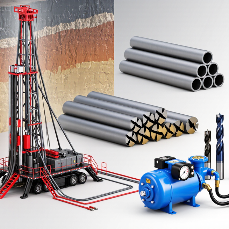
Define Well Depth, Hole Size, and Pressure Requirements
Before selecting equipment, define both measured depth and true vertical depth. Measured depth determines drillstring length and friction losses; true vertical depth helps estimate hydrostatic pressure. Record planned hole diameters by section, not just the final bit size. A 12¼-inch section, for example, needs compatible bits, stabilizers, drill collars, and casing clearance. Check the well plan for doglegs and expected cuttings loads, too. Small details matter.
Pressure needs deserve equal care. Calculate the expected formation pressure and circulating pressure for each section, then compare them with the rated working pressure of the mud pumps, surface lines, and well-control equipment. API Standard 53 addresses well-control equipment systems; use its applicable requirements alongside the approved well program. EIA’s January 2024 Drilling Productivity Report tracked basin-level new-well output per rig, including roughly 1,300 barrels per day in the Permian. That is a productivity measure, not an equipment-sizing rule. Don’t confuse the two. Pressure estimates also depend on fluid density, temperature, and changing downhole conditions. A spreadsheet can look precise and still inherit a bad assumption. Have qualified drilling personnel review the pressure envelope, equipment ratings, and section-by-section clearances before procurement.
How to Choose Oil Drilling Equipment - Define Well Depth, Hole Size, and Pressure Requirements
| Well Section | Illustrative Measured-Depth Range | Common Hole Size | Common Casing Size | Equipment Selection Considerations | Pressure Requirement |
| Conductor and surface section | Surface to approximately 2,000 ft (610 m) | 17½–26 in | 13⅜–20 in | Confirm the rig can handle the required large-diameter bits, casing, and conductor installation method. Check rotary-table or top-drive clearance and available circulation capacity. | Determine the required well-control equipment from the shallow-hole design and applicable regulations; depth alone does not determine the pressure rating. |
| Intermediate section | Approximately 2,000–8,000 ft (610–2,440 m) | 12¼–17½ in | 9⅝–13⅜ in | Match the rig’s lifting capacity, pump output, drill-string dimensions, and solids-control equipment to the planned hole and casing program. | Use the well-specific maximum anticipated surface pressure and the required pressure-control configuration to specify rated equipment. |
| Production section | Approximately 5,000–15,000 ft (1,520–4,570 m) | 8½–12¼ in | 5½–9⅝ in | Check drill-pipe and tool-joint compatibility, expected torque and drag, directional-drilling needs, and the rig’s capacity for the planned casing string. | Specify the BOP and associated well-control equipment against the calculated pressure case, not as a fixed function of hole size or depth. |
| Deep or slim-hole section | Approximately 10,000–20,000+ ft (3,050–6,100+ m) | 6⅛–8½ in | 4½–7 in | Evaluate drill-string strength, hook-load margin, hydraulic pressure losses, temperature limits, and the availability of compatible downhole tools. | Confirm pressure ratings for every pressure-containing component, including the BOP, choke manifold, valves, and connected lines. |
| Pressure-rating reference | Applicable at any depth | Not determined by hole size | Not determined by casing size alone | Common nominal BOP working-pressure rating classes include 5,000, 10,000, and 15,000 psi. Select the appropriate class using the approved well design and local requirements. | Calculate the pressure case from anticipated formation pressures, fluid columns, shut-in conditions, and the well-control design. Verify that the selected rating meets all applicable requirements. |
Planning note: Depth bands, hole sizes, and casing sizes are illustrative examples, not a standard well program. Final equipment specifications should be verified against the approved casing and drilling program, formation data, operating conditions, and applicable regulations.
Match Rig Capacity to Planned Depth and Maximum Hook Load
Choosing a rig by planned depth alone is a common mistake. Depth estimates how much drillstring may hang in the hole; it does not define the required hook load by itself. The IADC Drilling Manual lists common 5-inch drillpipe at about 19.5 pounds per foot. A 10,000-foot string therefore weighs roughly 195,000 pounds in air, before adding the bottom-hole assembly, connections, or casing. Mud buoyancy changes the suspended weight, while overpull and movement add operating loads. Check the numbers.
Compare the calculated maximum load with the rig’s rated hook load, and verify the rating against the hoisting-system documentation and API Specification 8C. Include the heaviest planned string, not just the routine drilling assembly. Allow for foreseeable operations such as stuck-pipe recovery and casing runs, but do not treat a larger rating as a substitute for a load calculation. A rig near its limit leaves little room for changing conditions. A very large rig may add cost without solving a depth problem. The estimate is imperfect unless the well plan states its assumptions: fluid density, string configuration, and required overpull. Recheck them when the plan changes.
Select Drillstring Equipment Under API Specification 7K
How to Choose Oil Drilling Equipment
Select Drillstring Equipment Under API Specification 7K
When selecting elevators, slips, rotary equipment, and related handling tools, verify that each item falls within API Specification 7K’s scope. Check the applicable edition, rated capacity, connection details, inspection records, and operating limits. Compare the equipment rating with the planned load, including expected handling conditions. A capacity number alone is not enough. The tool must also fit the string and rig setup.
The CDC and NIOSH report Fatal Injuries in the Oil and Gas Extraction Industry, 2003–2013, recorded 1,189 worker deaths across the period. That figure does not measure equipment failures, but it underscores why handling limits and maintenance records matter. Ask for traceable inspection documentation, and examine contact surfaces for cracks, deformation, or heavy wear. Confirm that the crew follows the manufacturer’s operating instructions and site procedures. In practice, paperwork can look complete while a worn latch gets missed. It happens.
Tips: Before mobilization, match each tool’s identification and rated load to the equipment list. Check fit with the actual tubular dimensions. Photograph questionable wear, then pause use until a qualified inspector assesses it. API compliance supports selection; it does not replace field inspection or sound judgment.
Choose BOPs Rated from 2,000 to 15,000 psi under API 16A
How to Choose Oil Drilling Equipment
Choose a blowout preventer (BOP) rated between 2,000 and 15,000 psi under API 16A only after confirming the well’s pressure requirements. The rating should meet or exceed the maximum anticipated surface pressure for the planned operation. A higher number is not automatically a better fit. Pressure matters.
Check the complete equipment specification, not just the headline rating. Confirm the BOP’s bore size, connection type, temperature range, and compatibility with the planned fluids and seals. These details affect whether the equipment can be integrated and operated as intended. A mismatch can complicate installation or performance. Details count.
Review the API 16A documentation, pressure-test records, and inspection history with qualified drilling and well-control personnel. Confirm that the selected configuration, including the stack and related components, suits the operating plan. A tidy rating on paper may not answer every field question; I would pause and verify any unclear limit with the equipment supplier and engineering team. Do not guess. Keep the pressure basis and supporting records available for the crew before the BOP reaches the rig floor.
Verify Rig Structures and Choke-and-Kill Systems to API 4F and 16C
Choosing oil drilling equipment means checking more than rated capacity. For rig structures, confirm that the design and fabrication documents identify the applicable API 4F edition and equipment scope. Compare the serial number and nameplate on the structure with its inspection and traceability records. Look closely at weld areas, bracing, and connection points; paint can hide small signs of damage. Paperwork matters, but it is not proof by itself. An independent inspection can help resolve gaps before equipment is accepted.
For choke-and-kill systems, verify that components are documented against the applicable API 16C requirements. Check pressure ratings, connection types, material records, and test reports across the assembled system—not just one valve. Confirm that hoses, lines, and fittings suit the expected operating conditions and match the system specification. Ask for clear records of pressure testing and maintenance, and investigate missing or inconsistent documents. One detail is easy to miss: a compliant component may still be unsuitable for a particular system. I would recheck compatibility rather than assume the paperwork settles it.
How to Choose Oil Drilling Equipment: Verify Rig Structures and Choke-and-Kill Systems
Reference pressure classes for choke-and-kill equipment, shown in psi and MPa. Confirm the required rating against well design, equipment nameplates, and the applicable API 16C edition.
Pressure classes shown are reference values, not a recommendation or proof of compliance. Separately verify rig structure design, inspection, and documentation against the applicable API 4F requirements. Select equipment only after confirming that its ratings and configuration suit the intended service.