What Is an Elevator Guide Rail Bracket?
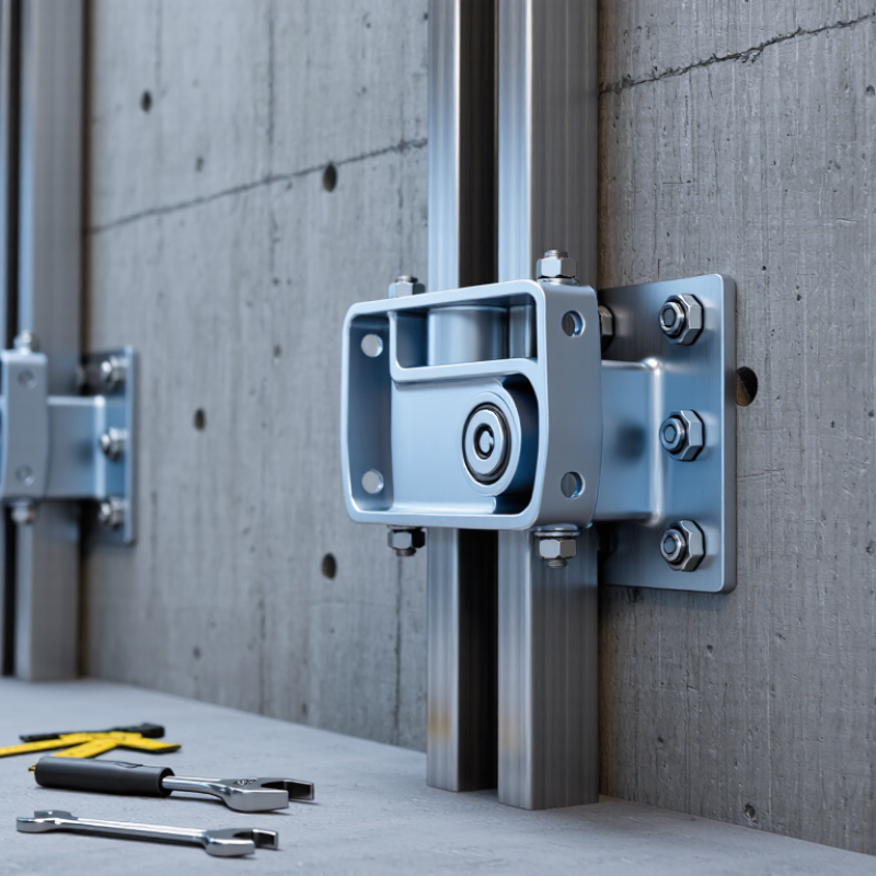
An Elevator Guide Rail Bracket is a small component with a demanding job: it secures the guide rail to the hoistway wall and helps keep the rail aligned as the car travels. Picture a steel bracket anchored beside a concrete shaft, holding a vertical rail against vibration and changing loads. If its position or fastening is wrong, the effects can reach beyond the bracket itself.
The scale of the wider industry makes dependable installation important. The International Energy Agency’s Buildings report estimates that buildings account for about 30% of global final energy consumption. That figure is not specific to elevators or rail brackets, but it underscores why building systems deserve careful engineering and maintenance. For elevator design and safety requirements, professionals consult standards such as ASME A17.1/CSA B44 and ISO 8100-1; project requirements still depend on the elevator, structure, and local conditions.
A guide rail bracket is not a decorative fitting. Its material, spacing, anchor selection, and installation position must suit the rail and the building substrate. Small details matter. This introduction does not include a named expert quotation because no verifiable quotation or source was provided; inventing one would weaken trust. The sections that follow explain what the bracket does, how it is selected, and which installation details deserve close review. One point bears repeating: alignment is unforgiving.
Definition and Load-Transfer Role of an Elevator Guide Rail Bracket
What Is an Elevator Guide Rail Bracket?
An elevator guide rail bracket is a steel fitting that secures a guide rail to a building’s supporting structure. It may connect the rail to a wall-mounted insert, beam, or other designed support. Small part. Big consequence. The bracket helps keep the rail aligned and limits unwanted movement as the elevator operates.
Its load-transfer role is straightforward, but important. Forces from the moving car or counterweight act on the guide rails through contact and guidance. The rails pass some of those forces into the brackets, which transfer them to the building structure through their connections. Brackets also help resist vibration and sideways forces, especially when the car travels or its safety gear engages. They do not simply carry the elevator’s full weight; the hoisting system supports that load.
The actual forces depend on rail spacing, bracket intervals, fasteners, and the strength of the supporting material. A bracket attached to sound concrete behaves differently from one fixed to a thin or poorly prepared surface. That detail can be easy to overlook. Proper design and installation require checking the complete load path, not just the bracket’s appearance. Alignment should also be checked during installation, since small offsets can affect how smoothly the car runs.
What Is an Elevator Guide Rail Bracket? - Definition and Load-Transfer Role of an Elevator Guide Rail Bracket
| Aspect | Description | Load-Transfer Role |
| Definition | A guide rail bracket is a structural support that connects an elevator guide rail to a building support, such as a hoistway wall or a structural fixing. | Provides an attachment path from the rail into the building structure and helps keep the rail in its intended position. |
| Typical parts | Depending on the design, an assembly may include a wall plate, bracket arm, rail clip or clamp, and fasteners. | The rail connection and building-side fixing work together to transmit support reactions; exact arrangements vary by elevator and building design. |
| Normal operating forces | Guide shoes or rollers on the car and counterweight act against the rails as the elevator travels. Changes in alignment and motion can produce forces on the guide system. | Forces acting on a rail are passed through its supports and brackets to the building structure. The bracket helps restrain rail movement. |
| Emergency braking loads | Where a car safety gear engages the guide rails, the resulting forces act through the rail system. The applicable load effects depend on the elevator design and safety gear arrangement. | The rail supports and their building connections must be designed for the loads specified for the installation; the bracket is one part of that load path. |
| Load path | A simplified path is: car or counterweight guide device → guide rail → rail connection → bracket → fasteners or anchors → building structure. | Each connection in the path must transfer its share of the design forces to the next supporting element. |
| Positioning and alignment | Brackets support the rail at locations established by the elevator layout and installation requirements. Rail alignment is checked during installation. | Properly installed supports help limit unwanted rail displacement and maintain the geometry needed for guided travel. |
| Design considerations | Design depends on the rail and bracket arrangement, support spacing, expected loads, building substrate, and the capacity of the connections. | The bracket, rail attachment, anchors, and supporting structure should be evaluated as a connected system for the specified installation. |
| Important distinction | Guide rails guide the car and counterweight. In a typical traction elevator, the suspension system carries the car and counterweight; guide rails are not the normal suspension path. | Brackets primarily support and restrain the rails. Loads applied to rails in other operating or safety conditions must be considered according to the elevator design. |
Note: Bracket configuration, support spacing, and design loads are installation-specific and should be confirmed using the elevator design documents and applicable requirements.
Bracket Positioning Along T-Rails: Typical Support Spacing of 1.5–2.5 m
What Is an Elevator Guide Rail Bracket?
Bracket Positioning Along T-Rails: Typical Support Spacing of 1.5–2.5 m
A guide rail bracket anchors the T-rail to the hoistway wall and helps resist forces from the car and counterweight. Typical layouts place brackets about 1.5–2.5 m apart. The range is a planning reference, not a universal requirement. Longer spans can increase rail deflection; tighter spacing adds anchors and installation work. Small details matter.
EN 81-20:2020 and ISO 8100-1:2019 require guide rail strength and deflection to be assessed for the lift’s design conditions; neither sets one fixed bracket interval for every installation. The final pitch depends on rail dimensions, car load, travel speed, bracket capacity, and the wall substrate. On site, installers check that brackets sit square, anchors engage sound concrete or structural steel, and rail joints follow the approved layout. A weak fixing can undermine an otherwise robust rail. That part is easy to overlook.
The 1.5–2.5 m range is useful when sketching a layout, but it needs verification against project calculations and installation instructions. Builders sometimes assume a regular rhythm will fit every shaft. It may not. Door openings, beams, and uneven walls can shift bracket positions, so the rail alignment and fixing capacity should be checked before drilling.
Bracket Types, Anchor Systems, and Shaft Materials
An elevator guide-rail bracket fixes the rail to the hoistway wall and helps maintain alignment as the car travels. Common designs include fixed brackets, adjustable brackets, and sliding arrangements that accommodate limited movement. Fixed types suit stable, accurately built walls. Adjustable types help installers correct small alignment errors. Small errors matter.
CTBUH’s 2023 Year in Review recorded 100 completed buildings at least 200 metres tall worldwide. That growth highlights the range of shaft conditions engineers must consider, though building height alone does not determine bracket spacing. Anchors may connect brackets to cast-in channels, embedded plates, or post-installed mechanical or adhesive anchors. ACI 318-19 Chapter 17 provides design provisions for concrete anchoring; the anchor must suit the substrate and calculated loads.
Shafts are commonly formed in reinforced concrete or structural steel, while some projects use other engineered wall systems. Bracket choice depends on rail loads, wall strength, tolerances, vibration, and installation access. EN 81-20:2020 sets elevator safety requirements, but it does not replace project-specific structural design. I would not trust a tidy drawing alone: site measurements and substrate checks can reveal details the plans miss.
What Is an Elevator Guide Rail Bracket?
Typical anchor options by shaft substrate
Guide rail brackets connect elevator guide rails to the shaft structure. Common forms include fixed or adjustable brackets; the required anchors depend on the substrate and project design. The bars count example fixing methods described here, not a performance rating or installation specification. Concrete may use approved mechanical or chemical anchors, structural steel may use bolted or—where permitted—welded connections, and masonry requires anchors approved for the specific wall. Confirm selections and spacing with the elevator design and applicable codes.
Rail Loads, Alignment, and Deflection Checks Under EN 81-20
What Is an Elevator Guide Rail Bracket?
A guide rail bracket fixes the elevator rail to the building structure and helps maintain its position under operating forces. Under EN 81-20:2020 and EN 81-50:2020, rail strength and deflection must be verified for relevant load cases. A bracket is not just a clamp: its spacing, fasteners, rail joint locations, and supporting wall all affect how loads travel into the structure.
A 1,000 kg payload represents about 9.8 kN of gravitational load, before adding car mass, dynamic effects, or uneven loading.
That figure is not the force on one bracket; engineers must calculate rail reactions for the specific installation. Check forces from normal operation and safety-gear engagement, then verify bracket bending, anchor capacity, and the substrate. Small errors matter.
Rail alignment should be measured vertically and across the shaft, because a slight offset can create binding, noise, or uneven wear. The European standards provide the verification framework, but project drawings and actual material properties determine the result. Record measured deflection and tolerances. Recheck after tightening; site conditions can change the reading.
T-Rail Dimensions and Tolerances Referenced in ISO 7465:2007
What Is an Elevator Guide Rail Bracket?
T-Rail Dimensions and Tolerances Referenced in ISO 7465:2007
An elevator guide rail bracket secures the rail to the shaft structure and helps maintain its position during installation and operation. The rail itself is a T-shaped steel profile. ISO 7465:2007 specifies dimensions and tolerances for these guide rails, including the head, web, and foot. Exact measurements depend on the rail’s designated profile, so installers should check the relevant standard table rather than rely on a generic sketch.
Small differences matter.
The head guides the car’s sliding shoes or rollers, while the foot provides a mounting surface. The web connects these sections and affects the rail’s overall geometry. Tolerances define the permitted variation from nominal dimensions; they are not optional targets for adjustment. A caliper can help check accessible dimensions, but it cannot confirm every profile or installation condition. Brackets must hold the rails in alignment without forcing them into position.
That sounds simple. It isn’t always.
Shaft surfaces, bracket spacing, and fastening can all affect the final alignment. For a specification or replacement decision, verify the rail type and dimensional values against ISO 7465:2007 and the project drawings. A table alone may not explain every site condition.