7 Trailer Cable Buying Tips for Global Buyers
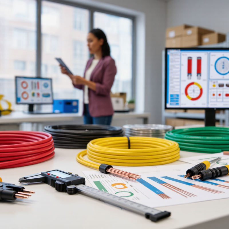
Buying trailer cable across borders is not a simple price comparison. A cable that looks suitable on a supplier’s screen still needs to match the trailer’s electrical load, installation space, and operating conditions. Small details matter. Check conductor material, wire gauge, insulation, temperature range, and resistance to moisture, abrasion, and road chemicals. Ask for current technical data sheets and test reports, then confirm that the documents match the exact cable offered.
Trailer-cable sourcing specialist Mara Chen puts it this way: “A cable that fits the drawing must still fit the road.” Treat that as a practical reminder, not a substitute for engineering review. A sample can reveal stiff insulation, unclear printing, or a jacket that feels thinner than expected. It cannot prove long-term performance on its own. Request traceable production details, discuss quality checks, and verify that any claimed approvals apply to the product and destination market. Requirements vary by application and location.
This guide shares seven checks for global buyers: defining specifications, comparing materials, reviewing supplier documentation, assessing environmental durability, confirming production consistency, planning shipping, and evaluating after-sales support. You may not get perfect answers from every supplier. That deserves a second look. A low quote can hide differences in conductor construction or testing scope, while an attractive brochure may leave key measurements unspecified. Clear questions help expose those gaps before an order is placed. Use the tips as a starting point, and involve a qualified engineer when the application has demanding electrical or environmental conditions.
Confirm System Voltage: SAE J560 Uses 12 V; ISO 1185 Uses 24 V
Voltage is the first compatibility check when buying trailer cable. SAE J560 uses 12 V; ISO 1185 uses 24 V. These systems are not interchangeable just because their plugs look similar. A mismatch can cause dim lamps, unreliable signals, or damage to connected equipment. Check the towing vehicle and trailer specifications before ordering. Look for voltage details on equipment labels, wiring diagrams, or existing cable documentation. If records are unclear, have a qualified technician verify the system with a suitable meter. Do not guess from wire colors alone; previous repairs may have changed them.
Small details matter. Confirm the connector standard and pin arrangement, then match the cable’s conductor size and length to the trailer’s requirements. A long run or multiple lamps can increase voltage drop, especially with undersized conductors. Inspect the cable route, too: tight bends, sharp frame edges, and exposed sections can wear insulation over time. In practice, buyers sometimes focus on connector fit and overlook voltage. That is an easy mistake, and one worth checking twice. If a trailer combines equipment from different systems, pause and confirm compatibility before connecting it. A neat-looking plug is not proof.
7 Trailer Cable Buying Tips for Global Buyers - Confirm System Voltage: SAE J560 Uses 12 V; ISO 1185 Uses 24 V
| Buying Tip | What to Confirm | SAE J560 | ISO 1185 | Buyer Action |
|---|---|---|---|---|
| 1. Confirm system voltage | Match the cable and connected equipment to the towing vehicle’s electrical system. | Commonly used for 12 V trailer lighting systems. | Specifies a 7-pole, 24 V connector system, commonly identified as Type 24N. | Check the vehicle and trailer specifications; do not assume a 12 V and 24 V setup is interchangeable. |
| 2. Verify connector standard and pin layout | Confirm the connector type, pole count, and pin functions at both ends. | Seven-pole connector commonly used in North American heavy-duty applications. | Seven-pole Type 24N connector used in 24 V applications. | Match both connector ends to the applicable standard and wiring diagram. The same pole count does not guarantee compatibility. |
| 3. Size conductors for the application | Consider circuit current, cable length, conductor size, and allowable voltage drop. | Choose conductors appropriate for the vehicle’s 12 V circuits and connected loads. | Choose conductors appropriate for the vehicle’s 24 V circuits and connected loads. | Use the equipment manufacturer’s current requirements and applicable electrical rules; avoid selecting cable by outside diameter alone. |
| 4. Select a suitable cable construction | Check conductor material, insulation, jacket, flexibility, and resistance to the intended service conditions. | Construction requirements depend on the specific cable and application. | Construction requirements depend on the specific cable and application. | Specify the operating temperature range and exposure to abrasion, moisture, oils, and road chemicals where relevant. |
| 5. Check length and routing | Allow sufficient reach through the full range of articulation without excessive slack or tension. | Route to avoid sharp edges, hot surfaces, pinch points, and moving components. | Route to avoid sharp edges, hot surfaces, pinch points, and moving components. | Measure the installed route on the vehicle and trailer, including the movement needed when turning. |
| 6. Inspect connector protection and strain relief | Confirm that the connector, cable entry, and mounting arrangement suit the expected environment. | Check that the mating connector and cable assembly are intended for the application. | Check that the mating connector and cable assembly are intended for the application. | Review sealing, corrosion protection, retention, and strain relief. Do not assume an ingress-protection rating unless it is specified for the product. |
| 7. Request documentation and test the assembly | Verify the stated standard, voltage rating, conductor details, and test information. | Confirm documentation identifies the SAE J560 configuration when required. | Confirm documentation identifies the ISO 1185 Type 24N configuration when required. | Before use, verify pin-to-pin continuity and correct circuit function with suitable test equipment. |
Important: Nominal system voltage is not the same as the instantaneous voltage measured at a vehicle. Confirm the electrical system and the ratings of all connected components before purchase or installation.
Related Posts
-
The Essential Guide to Choosing the Right Trailer Cable for Your Needs
-
Top 10 Trailer Cable Types Buyers Need to Know?
-

How to Choose the Right Wire and Cable for Your Project?
-
Why Choose the Right Outdoor Power Cable for Your Needs?
-

How to Choose the Right Flexible Cable Conduit for Optimal Electrical Safety
-
Best Cable Wire Types for Your Electrical Needs?
Our quality management system is registered to ISO 9001: 2015. Our team is dedicated to consistently providing quality service and products to our customers.